Power Monitor Project
I’ve always been curious how much electricity my various electrical appliances were using. I pay this large electricity bill monthly but am frustrated attempting to track down the contributors to the power usage. I have never seen a low cost power monitor – one that you plug an appliance into that measures kwh consumed over a period of time.
One of the reasons for the lack of such devices is that power measurement is a little trickier than measuring volts and amps. Using RMS ampere readings to calculate power is only accurate if the load is purely resistive, and even then it does not take into account the duty cycle of the appliance. It may only run 5 minutes a day.
This article describes a simple power monitor based on a 68HC11 microcontroller with a 2 x 16 LCD readout. The electronics are totally isolated from the 120VAC mains by transformers.
I started this project off by looking for available chips that might do what I was looking for. This seems to be a very new category. I found possible contenders from Cirrus Logic (CS5460) and Analog Devices. Each are essentially a fixed function microcontroller consisting of a dual hi-res A/D converter, some arithmetic functions and either serial or frequency outputs. The Cirrus chip had both a synchronous serial output and a frequency proportional to watts output – the Analog Devices chip just had the latter (I have since discovered they make a serial device as well). Cirrus seemed to have more potential and offered samples so I took them up on it. It is available only in a 24 pin SSOP package – not a good thing for experimenters. I was able to find an SSOP to DIP converter card from a company called Aprilog.com – a little expensive ($10 each) but it did the trick nicely. These can be easily soldered by the way. I use solder flux and have successfully installed several of these high density surface mount components.
The Cirrus documentation was quite helpful – I learned how power measurements consist of the instantaneous voltage times the instantaneous amperage. RMS voltage and current is also calculated and the "apparent" power calculated as the product of the two. The real power will be different than apparent power if the load is reactive – inductive or capacitive. Motors fall into the inductive category. The result is a phase shift between the voltage and current and results in negative products of instantaneous volts and amps cancelling positive products, reducing the real power. The ratio of real power to apparent power is the "power factor". I have found this to be a significant factor in motorized appliances. The Cirrus chip is bi-directional – it can tell if you are consuming or producing power.
Amperage measurement is done using a Coilcraft CS60-010 current transformer. This is a small coil through which a single AC conductor is run. The coil puts out about 150 mV P-P at 15 amps. This is a good match for the Cirrus chip which has two programmable ranges of 0-30 or 0-150 mV. A shunt resistor could be used but I much prefer the isolated design provided by the coil.
Voltage is measured through a small DC power supply (obtained by hacking apart a spare wall wart). I used this both for the voltage measurement (using a resistor divider to get down to 150 mV) and as the system power supply via a Maxim MAX667 5 volt regulator. If you have a choice, be sure to get a power supply with a center tapped transformer – most wall warts work this way. I used one without a center tap and with a full-wave bridge instead. This does not result in an accurate wave referenced to system ground. I finally decided it was good enough for my purposes. Again, an across the line voltage divider could be used, but I preferred the isolation provided by the transformer.
The Cirrus chip provides both a synchronous serial output and a pulse output where each pulse represents a defined quantity of energy. The pulse signal would theoretically be easier to use – however you need to get the serial link working anyway to configure the registers. I got the pulse working but quickly moved on to the full serial data mode. The spec appeared to be compatible with SPI but I was never able to get it working properly. I then bit banged a serial link , which, after a few evenings, I managed to get fully operational.
I had considerable problems getting clean input voltage and current signals. Both voltage and current measurements looked fine on the scope until hooked up to the chip. The signals then got very noisy. I was using my hair dryer calibration tool ( the perfect 15 amp / 7 amp test source). The voltage problems I believe were due to common mode voltage resulting from my full wave bridge supply.
Then, as seems to often happen at the 90% operational point, disaster struck. I managed to fry the voltage input. With only one chip sample, I was pretty much dead. Cirrus’ web sample page only returned a "Sorry, only one sample every 90 days" message. The only company that I could find that carried the chip was Insight Electronics – not available until October plus a $50 minimum order. I sent off a frantic plea for help to Cirrus. They did send two more samples but only after I had completed version 2 of my project.
With my newfound insight into power measurement, I decided I could do the calculation myself using the A/D on my 68HC11. Granted its only 8 bit, not 20 bit, but it seemed like an interesting challenge that would be good enough for my purposes. I had a challenge using an OP amp to convert my low level current signal to 0 – 5 range (actually 1.5 to 3.5 – I should have used a rail-to-rail op amp). It was relatively simple to do the calculations. I ran the A/D conversion / instantaneous calculation loop as fast as possible – these calcs consist primarily of adding to accumulators. I then stop once a second to calculate RMS voltage, RMS current, average power, power factor, duty cycle, watt hours, cost since reset and cost per day and display the results. I could do about 900 energy calculations per second this way – more than enough to give decent average results. I had to resort to 4 byte long arithmetic to look after the RMS and energy accumulators.
Calibration was simple – I used my hair dryer calibrator. I set it to full power and set my current gain factor to give a 15 amp result. I used a similar process with voltage and watts.
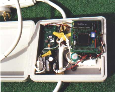
I used a serial Backpack 2 x 20 LCD readout to display the results along with a pushbutton that toggled between primary and secondary information screens. The microcontroller board used was a Zorin 68HC11 board with 32K SRAM. I wire-wrapped a small attachment board with all the other components. The programming was done using Imagecraft C – see the attached listing. I had initially though I could pull it off in a 2K EEPROM on a 68HC811E2, but I know now that would have been tough. Including the long math and printf routines pushed it well outside that range. I added a large capacitor for non-volatile memory. The components were mounted in a plastic case (actually a CD storage case) that just happened to be within reach when I started thinking about an enclosure. I cut the enclosure into an extension cord.

The unit simply resets to zero on power up and starts to accumulate kwh. It displays Average Power (over the last second) and watt-hours, cost and running time in hours since reset. The secondary display shows RMS amps, RMS voltage, Duty cycle and power factor. The unit has been around the house measuring various devices. My main computers draw about 300 watts (includes my Digital 20" monitor which uses about 180 watts itself and lots of peripheral stuff), my backup machine uses about 225 watts. It costs me about 50 cents per day to run my main machine at a 40% duty factor. Doesn’t seem like a lot, but that’s one appliance among many adding about $15 per month to my power bill. The second fridge draws about 2 kwh per day, about 20 cents per day, $6/month, $72/yr. We may not reduce our power bill a whole lot but at least I’ll have the peace of mind knowing where its going.
Take a look at the power usage survey results of our house in
Results.htm. I found a few surprises, such as a waterbed that was costing us almost a dollar a day.I wouldn’t use this for commercial power transfer. The calculations are a little crude. No calculations are done during the average calcs / display period - it is assumed the values stay about the same. The measurement does suffer from the 8 bit A/D – the resolution is about plus/minus 10 watts. This is OK for what I’m doing. I have been thinking of tying it to my main distribution box – I would need the extra resolution to pull that off and would resurrect the Cirrus chip. Clamp-on current transformers are available for about $60 each that would make this a little easier. It would also be fairly simple to add more current monitor transformers, allowing one to monitor multiple lines. A power line communication interface connected back to my PC and I could do real time power monitoring.